DEEP IIoT Starter-Kit Getting Started Guide
The starter kit contains the following interconnectable boards:
- Zest_Core_STM32H743ZG,
- Zest_Radio_Heracles224G,
- Zest_Sensor_4-20mA,
- Zest_Power_12-48V-to-10V,
- Zest_Security_SecureElement,
- Zest_RTC_RV-8803-C7.
Step 1 – Zest_Core_STM32H743ZG assembly
Hardware:
- 1x Zest_Core_STM32H743ZG,
- 4x M3 female to female round plastic standoffs, 8 mm,
- 2x M3 male to female hex metal standoffs, 20 mm,
- 2x M3 metal screws, 6 mm.
Assembly: 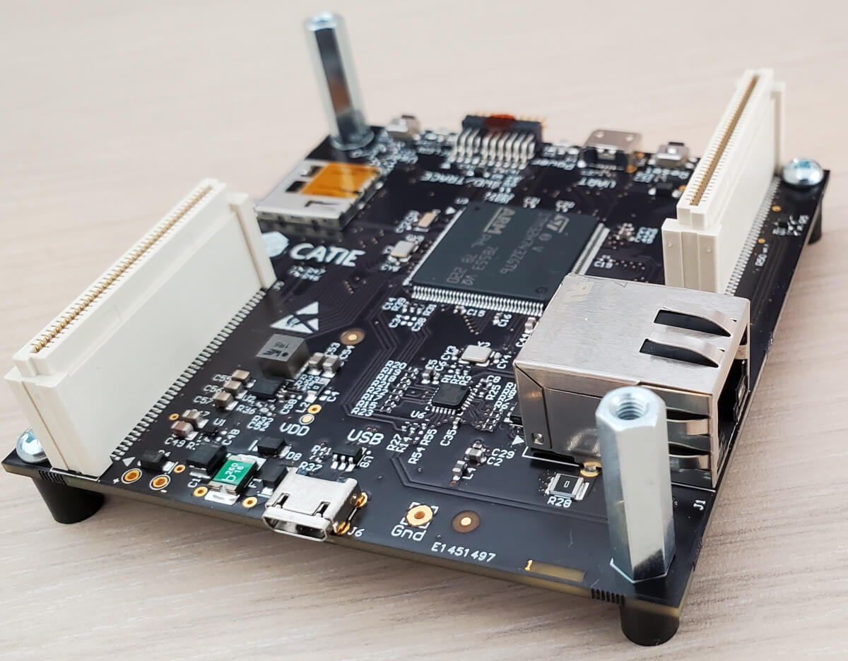
Step 2 – Zest_Sensor_4-20mA configuration
The Zest_Sensor_4-20mA can interconnect 4 analog sensors. The user can choose 0-5V, 0-10V or 4-20mA interfaces. Each channel can be configured with a jumper on J7 to J10. 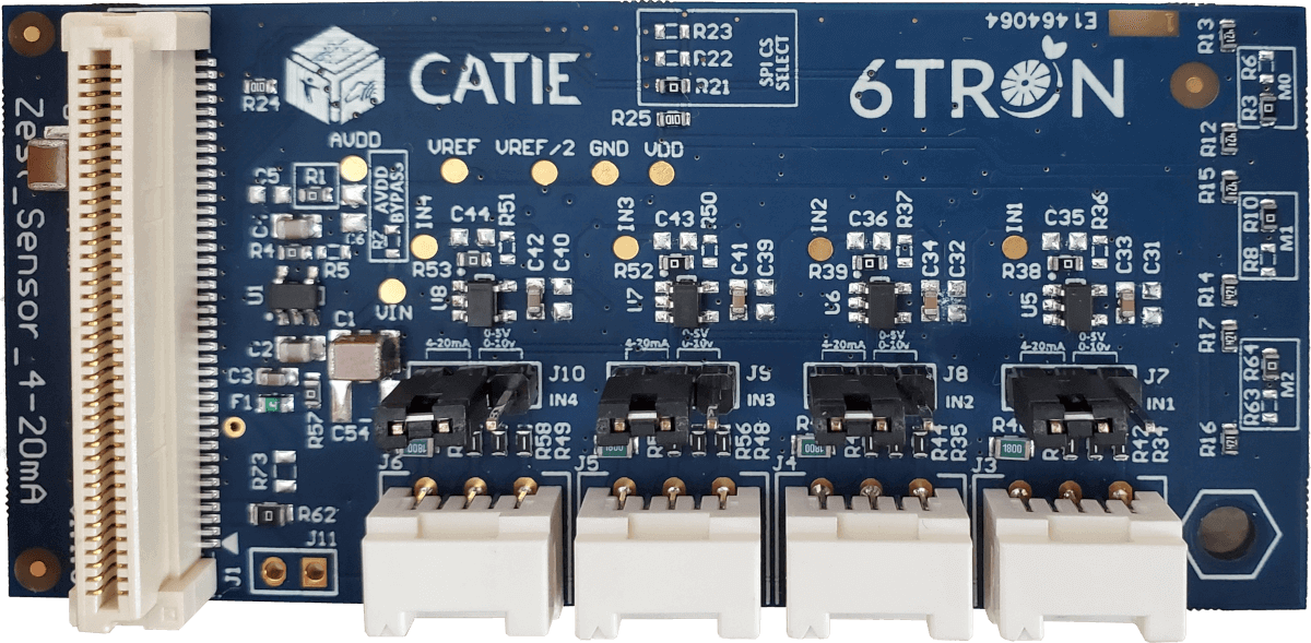
The pinout on J3 to J6 is the following:
| 1 | 0-10V |
|---|---|
| 2 | Sensor supply |
| 3 | 0-5V |
| 4 | Gnd |
| 5 | 4-20mA |
Step 3 – Boards assembly
Stack the different boards and screw them with standoffs.
On P1:
- Zest_Sensor_4-20mA
- Zest_Security_SecureElement
- Zest_RTC_RV-8803-C7
On P2:
- Zest_Power_12-48V-to-10V
- Zest_Radio_Heracles224G
Assembly should look like pictured below.
On P1: 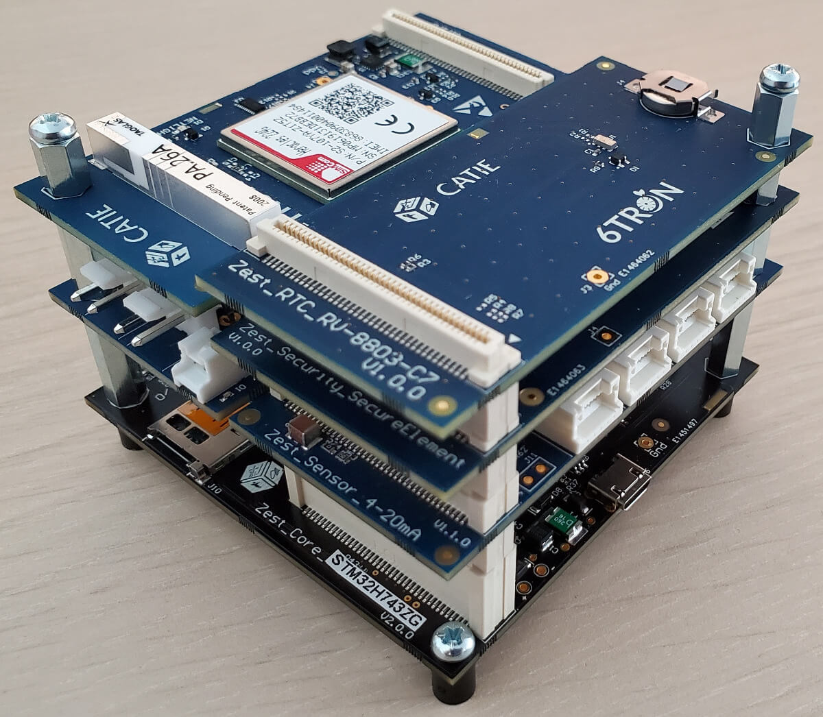
On P2: 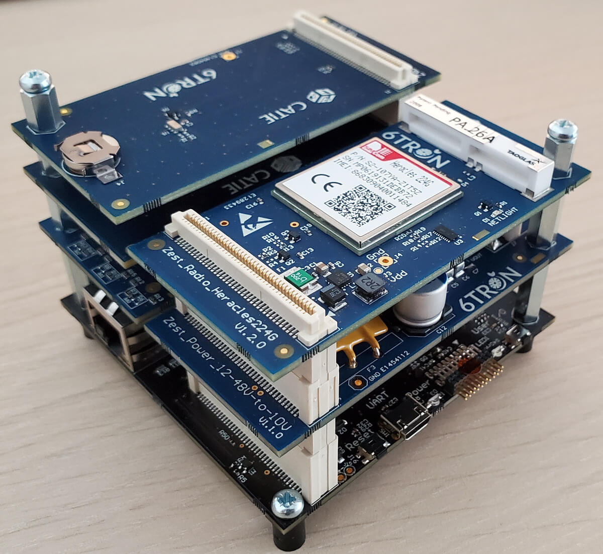
Step 4 – Power on
Connect the different analog sensors to the J3 to J6 ports on Zest_Sensor_4-20mA thanks to ZER-05V-S JST connectors.
Connect the external power source (12 to 48V, depending on the sensors used) on the J6 connector of the Zest_Power_12-48V. You need a JST VHR-2M connector.